Combined Bearings
Lifting and handling in a economical way.
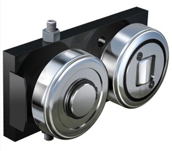
Adjustable Combined Bearing unit Type JC
for all standard profiles

Production Information
Advantages:
• Min. clearance between bearing unit and profile
• Higher positioning accuracyAssembly/Adjusting
Attention: Avoid giving to high pay loads to the adjustable bearing. (Risk of profile wear out.)
• The unit will be assembled by the flange plate.
• The position of the bearing must be at the load opposite side. The main forces should be on the radial bearing of the Combined Bearing.
• The adjustable bearing will be adjusted and finally secured.
Advice: Adjust the adjustable bearing with a clearance of 0.05 to 0.1 mm to the profile.
Test: The carriage should run smoothly in the profile without big resistance.
C = Dynamic load capacity radial bearing (ISO 281/1), CO = Static load capacity radial bearing (ISO 76), (Combined Bearing)
CA = Dynamic load capacity axial bearing (ISO 281/1), COA = Static load capacity axial bearing (ISO 76), (Combined Bearing)
FR = Load capacity radial bearing max. allowable force between bearing and profile,
FA = Load capacity axial bearing max. allowable force between bearing and profile (Combined Bearing)
Order example
JC 4.054 [Combined Bearing] · Standard 0 [Profile] · DS-0-0,5 [Washer type DS]Profiles
Standard 0 Nb |
|
weight/m |
10,5 kg |
Wx: |
32 cm3 |
Wy: |
6 cm3 |
ix: |
3,2 cm |
ey: |
1,3 cm |
lx: |
137 cm4 |
ly: |
15 cm4 |
iy: |
1,0 cm |
Standard 1 Nb |
|
weight/m |
14,8 kg |
Wx: |
53 cm3 |
Wy: |
11 cm3 |
ix: |
3,8 cm |
ey: |
1,5 cm |
lx: |
273 cm4 |
ly: |
27 cm4 |
iy: |
1,2 cm |
Standard 2 Nb |
|
weight/m |
20,9 kg |
Wx: |
81 cm3 |
Wy: |
15 cm3 |
ix: |
4,3 cm |
ey: |
1,5 cm |
lx: |
493 cm4 |
ly: |
38 cm4 |
iy: |
1,2 cm |
Standard 3 Nb |
|
weight/m |
28,6 kg |
Wx: |
128 cm3 |
Wy: |
27 cm3 |
ix: |
4,8 cm |
ey: |
2,0 cm |
lx: |
865 cm4 |
ly: |
89 cm4 |
iy: |
1,5 cm |
Standard 4 Nb |
|
weight/m |
36,0 kg |
Wx: |
190 cm3 |
Wy: |
39 cm3 |
ix: |
5,7 cm |
ey: |
2,2 cm |
lx: |
1494 cm4 |
ly: |
150 cm4 |
iy: |
1,8 cm |
Standard 5 Nb |
|
weight/m |
42,8 kg |
Wx: |
250 cm3 |
Wy: |
48 cm3 |
ix: |
6,3 cm |
ey: |
1,9 cm |
lx: |
2185 cm4 |
ly: |
205 cm4 |
iy: |
1,9 cm |
Standard 6 Nb |
|
weight/m |
52,3 kg |
Wx: |
340 cm3 |
Wy: |
57 cm3 |
ix: |
7,1 cm |
ey: |
2,0 cm |
lx: |
3423 cm4 |
ly: |
270 cm4 |
iy: |
2,0 cm |